Application Note BATT0001
The material development process is for mixing the raw materials evenly and crushing them. To check the raw materials, XRD and XRF are often used.
PHASE ID ANALYSIS OF LPS AND COMPOSITION ANALYSIS OF SI ANODE
1. Phase ID analysis of LPS with non-ambient XRD
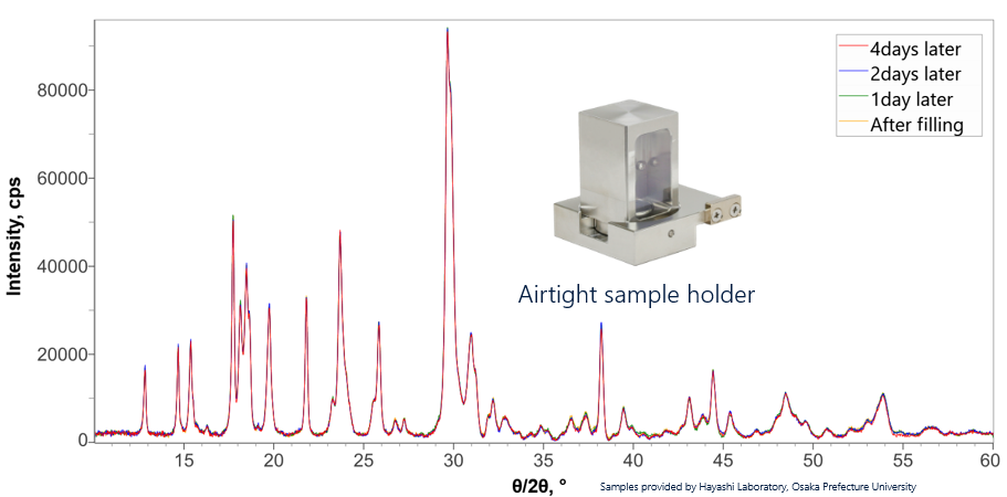
Li7P3S11(LPS) is a sulfide-type solid electrolyte that is expected to be a high-performance electrolyte due to high electroconductivity. One of the challenges with LPS is that it must be analyzed in an inert atmosphere as it reacts with moisture in the air to hydrogenate the sulfide. Therefore, an airtight sample holder was developed that allows easy filling and sealing in a glove box prior to analysis. The measured XRD data (shown below) was collected on the same LPS sample over a period of four days after mounting in the airtight holder. All the measured diffraction profiles are essentially the same. The airtight sample holder is a good choice for LPS analysis and can be used for any materials that react with components in the air.
Stability test of Li7P3S11 (LPS) using the air tight sample holder
2. Chemical composition analysis of Si anode with WDXRF
Non-destructive and precise elemental analysis from main components to trace impurities down to ppm-level. Standardless FP analysis method enables simple and quick quantification excluding calibration curves. Trace Al and Fe in Si-based anode can be clearly detected using WDXRF with Rigaku's ZSX Primus IV spectrometer. Carbon amount can be estimated for C-coated SiO anode.
Standardless FP analysis method enables simple and quick quantification of the elements from main components to trace impurities down to 10 ppm.
Sample: SiO anode (ppm)
|
Al |
Fe |
Zr |
|
|
XRF |
(39) |
(80) |
174 |
|
ICP |
11 |
14 |
129 |
Sample: C-coated SiO anode (ppm)
|
(ppm) |
Al |
Fe |
Zr |
|
XRF |
(40) |
134 |
146 |
|
ICP |
16 |
23 |
175 |
Sample: C-coated SiO anode (mass%)
|
(mass%) |
C |
|
XRF |
2.1 |
|
BET |
1.6 |
Standardless FP analysis results for SiO anode material samples: the amount of carbon coating and trace impurities. The values inside the parentheses are for reference. The ICP analysis or BET analysis values are shown.
WDXRF spectra of Si and SiC anode materials
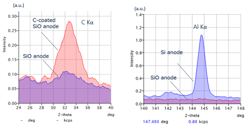
Carbon is detectable. Al impurities in Si-based anode samples can be analyzed using wavelength dispersive XRF (WDXRF). Achievement of this application is difficult with energy dispersive XRF (EDXRF).
3. Chemical composition analysis of NMC cathode with WDXRF
Wavelength Dispersive X-ray Fluorescence Spectroscopy (WDXRF) enables non-destructive and precise elemental analysis from major components to trace impurities down to ppm levels. The use of Standardless Fundamental Parameters (FP) analysis enables simple and quick quantification without the requiring sample-specific calibration curves. The results from WDXRF studies of Ni/Co/Al (NCA) and Ni/Co/Mn (NMC) molar ratios for the Lithium cathode materials NCA and NMC (shown below) are comparable with ICP-MS analysis. Trace amounts of Fe in NMC cathode can be clearly detected using WDXRF with Rigaku's ZSX Primus IV spectrometer.
WDXRF standardless FP analysis method enables simple and quick elemental quantification from major components to trace impurities down to 10 ppm.
Sample: NCA (0.80/0.15/0.05)
| Al | Co | Ni | |
| XRF | 0.042 | 0.156 | 0.803 |
| ICP | 0.05 | 0.15 | 0.80 |
Sample: NMC (0.85/0.10/0.05)
| Al | Co | Ni | |
| XRF | 0.056 | 0.098 | 0.846 |
| ICP | 0.05 | 0.10 | 0.85 |
Sample: NMC (0.50/0.20/0.30)
| Mn | Co | Ni | |
| XRF | 0.309 | 0.201 | 0.490 |
| ICP | 0.30 | 0.20 | 0.50 |
Standardless FP analysis results for cathode material samples. The results are shown in molar ratios as x values in LiMxO2. The ICP analysis values also shown.
WDXRF spectra of NCA and NMC cathode materials
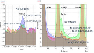
Fe impurities in NMC cathode samples, which are difficult to detect with energy dispersive XRF (EDXRF) due to peak overlapping with Mn Kβ line, can be analyzed using wavelength dispersive XRF (WDXRF).
4. Calcined reaction temperature of NMC with in-situ XRD
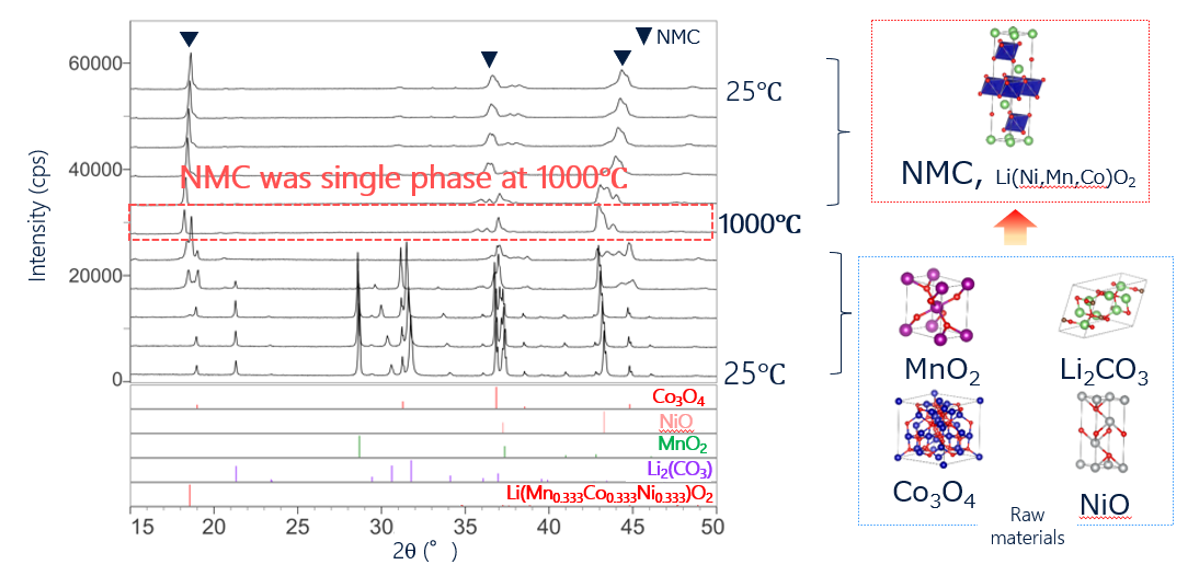
Solid-phase reactions, for example, calcination during synthesis of cathode materials, can be analyzed by performing in-situ XRD measurements during heating. The in-situ measurements make use of single heating run rather than multiple batch sampling as required for offline analysis. The raw materials of Co3O4, NiO, Li2(CO3), and Li(Mn0.333Co0.333Ni0.333)O2 were mixed and then analyzed in-situ using XRD while heating the sample. From the XRD profiles, it was found that a calcination process started at 600°C, and pure NMC cathode material was obtained at 1000°C. Using in-situ XRD during heating, phase transition processes can be observed continuously without batch sampling at each temperature.
Observation of synthesis reaction for cathode material by in-situ XRD measurements during heating
5. Crystallite and particle size analysis of Si anode with XRD
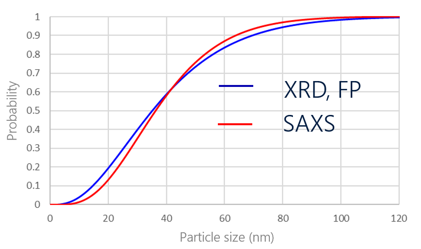
Si anode material is expected to be a high-capacity material. Nanoparticle formation of Si anode material is being studied to suppress the severe volume expansion that occurs during the discharge/charge process. While there are several analytical methods for the measurement of particle size, SAXS is particularly good for the analysis of nanoparticles. The particle size of Si anode material was calculated to be 39 nm by SAXS. In addition, its crystallite size, calculated by the FP method from its XRD profile, was calculated to be 40 nm. The Si anode material used for this analysis can be regarded as single-particle because the particle size was almost the same as the crystallite size.
Analysis results of particle and crystallite sizes of Si anode by FP method and SAXS
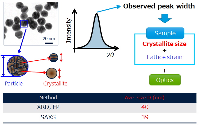
Particle and crystallite size distributions of Si anode calculated by FP method and SAXS
