Application Note XRD2001
Introduction
The crystallinity and preferred orientation of metal thin films significantly influence their physical properties. θ-2θ scans using the X-ray diffraction method and pole figure measurements are effective for evaluating these properties. When depositing thin films, if the substrate temperature is increased and then returned to room temperature, residual stress is generated due to the difference in thermal expansion coefficients between the film and the substrate. Understanding this residual stress is important for evaluating physical properties. Here, we present an example of evaluation this property using pole figures and residual stress measurements (sin²ψ method).

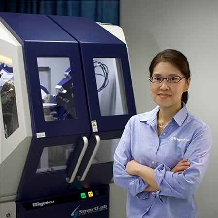
Figure 1: SmartLab SE with HyPix-400 detector and χφ attachment
Experiments
A thin gold film on a silicon substrate (approx. 20 x 20 mm in size) was used for this evaluation. The X-ray diffractometer was SmartLab SE with Cross Beam Optics (CBO) and HyPix-400 high-speed detector. The χφ attachment was employed (Figure 1). For the optics and slit conditions, the pole figure measurement used Bragg-Brentano focusing geometry with a Schulz slit; for phase identification and residual stress measurement, parallel beam geometry was used with a Parallel Slit Analyzer (PSA) 0.5° on the receiving side for the residual stress measurement.
Table 1: Optical system and slit configuration
|
Application |
Scan mode |
Incident optics |
Receiving optics |
|
Phase ID |
1-D |
Selection slit PB + IS 0.1 mm |
(No PSA) |
|
Texture / pole figure |
0-D |
Selection slit BB + Schultz slit |
10 mm (RS1 & RS2) |
|
Residual stress |
0-D |
Selection slit PB + LLS 2 mm |
PSA 0.5° |
For phase identification and peak selection, a general θ-2θ scan was performed over a range of 30° to 120° (2θ).
For the pole figure measurement, three different lattice planes were selected: Au 111, 200, and 220, with estimated peak positions at 2θ = 38.3°, 44.4°, and 64.6° based on actual measurements and database values.
The residual stress measurement utilized the side-inclination method, employing the fixed ψ method for diffraction peak measurement, which symmetrically scans incident X-rays and the detector relative to the lattice plane normal. For peak evaluation, smoothing, background removal with a model of linear connected endpoints, and Kα2 removal were performed beforehand, and the center of gravity method was used to determine peak positions. Scan speed was optimized to count at least 5,000 counts for peak top intensity.
Results and discussion
Figure 2 shows the results of the θ-2θ scan. Along with the 400 diffraction peak of the silicone substrate, strong diffraction peaks corresponding to gold’s 111 and 222 planes were observed. This result indicates that the gold thin film is strongly oriented in the (111) plane.

Figure 2: General measurement profile of gold thin film on a silicon substrate
Figure 3 presents three pole figures of the gold thin film. The presence of a pole at the center of the 111 pole figure confirms that the film is (111)-oriented. This result is consistent with the findings shown in Figure 2. Additionally, the observation of ring-shaped poles in each pole figure measurement indicates that the orientation type is uniaxial (fiber) texture. The peaks appearing at ψ = 55° in the 200 pole figure and at ψ = 37° in the 220 pole figure correspond to the 200 and 220 peaks of the (111)-oriented structure, respectively. An Orientation Distribution Function (ODF) analysis was performed based on the three pole figures, and the results of the simulated pole figures for the three measured planes are shown in the Simulated section of Figure 3. The pole figures obtained from the measurements closely match the simulated pole figures for the (111)-oriented texture, confirming that the gold thin film exhibits a (111) fiber texture.

Figure 3: Pole figures of Au 111, 200, and 220, Experimental (top) and Calculated (bottom)
Figure 4 shows the diffraction peaks and their corresponding ψ angles calculated under the assumption of (111) orientation using RS Viewer software. For residual stress measurements, it is necessary to select diffraction planes that exhibit diffraction at two or more ψ angles and have peaks at as high 2θ angle as possible. In this study, the 422 diffraction peak at 2θ = 135.4°, with ψ angles of 19.5° and 61.9°, was selected.
%20orientation.jpg?width=798&height=479&name=XRD2001%20Figure%204%20The%20distribution%20of%20gold%20diffraction%20peaks%20and%20psi%20angles%20calculated%20under%20the%20assumption%20of%20(111)%20orientation.jpg)
Figure 4: The distribution of gold diffraction peaks and ψ angles calculated under the assumption of (111) orientation. The two peaks marked with circles correspond to the (422) peak.
The selected ψ angles were compared with the simulated 422 pole figure obtained from the ODF analysis results (Figure 5). The presence of ring-shaped peaks at ψ = 19.5° and 61.9° further suggests that peaks are expected to be observed at these ψ angles.

Figure 5: The simulated Au 422 pole figure obtained from the ODF analysis results.
Figure 6 shows the obtained residual stress measurement results. It can be observed that the diffraction peaks shift to lower angles as the ψ angle increases. This indicates that the lattice distance d-value increases with the tilt of the ψ angle.
.jpg?width=1632&height=1162&name=XRD2001%20Figure%206%20Residual%20stress%20measurement%20profile%20of%20Au%20(422).jpg)
Figure 6: Residual stress measurement profile of Au (422) at ψ = 19.5° and 61.9°
Figure 7 shows the sin²ψ plot created from the obtained diffraction peak angles and ψ angles. Assuming Young's modulus of gold as 78,500 MPa and a Poisson's ratio of 0.42, the estimated residual stress value was approximately 58 MPa in tensile stress.

Figure 7: sin²ψ plot of gold thin film
Summary
θ-2θ scans, pole figure measurements, and residual stress measurements of the gold thin film on a silicon substrate were conducted using SmartLab SE. The results revealed that the gold thin film exhibits a (111) fiber orientation. Additionally, the residual stress in the gold thin film was found to be approximately 58 MPa in tensile stress. These findings demonstrate that X-ray diffraction measurements can provide valuable insights into the phase, orientation state, and residual stress of thin films. SmartLab Studio II’s Stress Plugin supports multiple HKL methods that are applied to weakly or non-textured thin films.