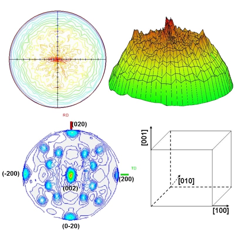
Texture and Pole Figures
Distribution of crystallographic orientations
In many cases, crystallographic texture (preferred orientation) can be introduced into a material during the fabrication process. For example, when steel sheets are rolled in the manufacturing process, a sheet texture is often produced. Since texture can affect a material's properties by introducing structural anisotropy, it is desirable to measure a material's texture.
Contact Us
Whether you're interested in getting a quote, want a demo, need technical support, or simply have a question, we're here to help.