Application Note B-XRD3007
Introduction
Multilayer ceramic capacitors (MLCC) consist of a layered structure of barium titanate (BaTiO₃) as the dielectric material and Ni as the internal electrode material. Because Ni and BaTiO₃ have different coefficients of thermal expansion, internal stresses are known to develop in MLCC after firing. In recent years, the miniaturization and increased capacitance of MLCCs have resulted in thinner BaTiO₃ dielectric layers and a greater number of stacked layers, making the structure more susceptible to the development of residual stresses.
The outer portion of an MLCC plays an important role in protecting the stacked internal electrode region and mitigating and distributing residual stresses. Therefore, evaluating residual stresses in this region is important for understanding the mechanical reliability of MLCC and the initiation and propagation behavior of cracks. Furthermore, as MLCC becomes smaller, it can be difficult for a general-purpose laboratory X-ray diffractometer equipped with micro-area optics to focus X-rays to the required beam size. In addition, the alignment accuracy between the X-ray irradiation position and the rotation axis can become a concern.
In this example, tri-axial stress analysis of MLCC was performed using the DicifferX Microarea Edition, a micro-area X-ray diffractometer equipped with a 20 μm-diameter X-ray beam that has a rotation-axis alignment accuracy of less than 10 μm.
Measurement and results
Two identical samples were cut to expose the layered structure of the internal Ni electrodes and the dielectric material (BaTiO₃). The sample cut with the surface without the external electrode was defined as the Z direction, while the sample cut with the surface containing the external electrode was defined as the Y direction (Fig. 1). The cut surfaces were then mechanically polished, followed by final polishing using an ion milling system.
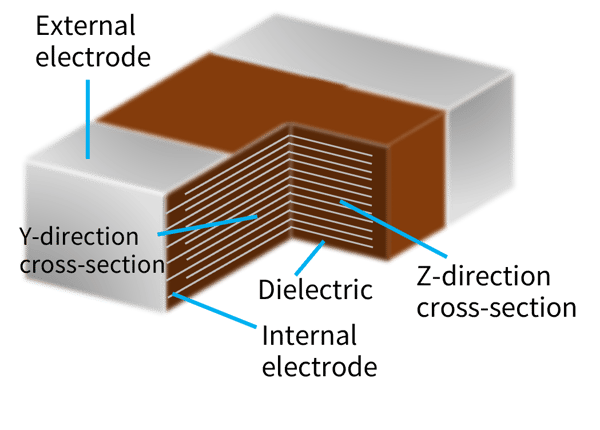 Fig. 1: Structure of the MLCC and directions of the measured cross sections
For the sample aligned in the Z direction, measurements were performed at two locations, on the corner and on the edge of the outer BaTiO₃ portion, which consists solely of BaTiO₃ and covers the inner section comprising the layered structure of the Ni internal electrodes and BaTiO₃ (Fig. 2). In a conventional tri-axial stress analysis, the in-plane rotation axis (φ-axis) is rotated in 45° increments, and ψ is measured at three to four points for each φ position (Table 1).
The Z-direction sample was measured using the side-inclination method, in which ψ is varied by rotating the inclination axis (χ-axis). Since the X-rays are incident obliquely on the sample surface at an incident angle ω and the χ-axis is also driven during the side-inclination measurement. The irradiated width becomes larger than under normal incidence. Because the width of the outer BaTiO₃ portion was 100 μm, a 10-μm collimator was used, with the measurement conditions adjusted to obtain an irradiated diameter of 20 μm under normal incidence.
The obtained Debye rings were divided into segments (Fig. 3). From the ψ and φ values at each segment and the results of the 2θ peak search, the shear stresses σ₁₂, σ₁₃, and σ₂₃ can be determined in addition to the normal stresses σ₁₁ and σ₂₂.
Figure 2 shows the results of the tri-axial stress analysis. Shear stress σ₁₂ was observed at both the corner and edge positions, with a higher stress value at the corner. It is also possible to calculate the principal stresses, for which the shear stress becomes zero (Fig. 4).
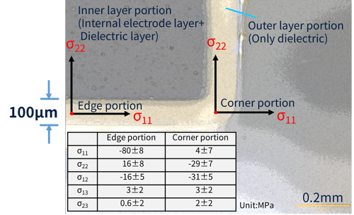 Fig. 2: Measurement positions and tri-axial stress analysis results for the MLCC cross section in the Z direction
Table 1: Example of φ and ψ positions for tri-axial stress analysis measurements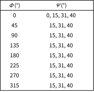
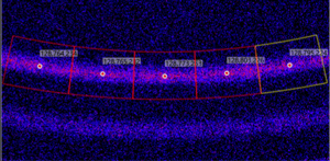 Fig. 3: Two-dimensional diffraction image and segmentation of the Debye ring
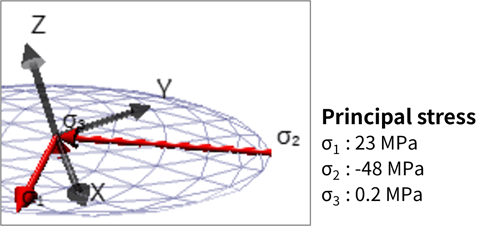 Fig. 4: Principal stress analysis results at the corner
Next, using the sample oriented in the Y direction, measurements were performed at five locations in the outer BaTiO₃ portion, as indicated by the red circles in Fig. 5. This sample was measured using the iso-inclination method, in which ψ was varied by changing the incident angle ω. The DicifferX Microarea Edition enables iso-inclination measurement with positive ψ, in which the ω-axis is moved in the positive direction. Compared with the side-inclination method, this positive-ψ iso-inclination method enables measurement with less spreading of the irradiated area on the sample surface.
The results showed clear differences in the residual stress values among the five measurement positions. At Positions 1 and 2, which are located far from the ends of the internal electrodes, almost no shear stress was observed, while σ₁₁ showed a high compressive stress. At Positions 3 and 4, high tensile stress was observed in σ₂₂, and the shear stress σ₁₂ was higher than that at Positions 1 and 2. This may be attributed to the fact that Positions 3 and 4 are located between the ends of the internal electrodes and the external electrode. The difference in the constraints imposed by these two structures is considered to change the direction of stress, resulting in an increase in the shear stress.
Position 5 was located very close to the external electrode, at a distance of 30 μm. Therefore, the high shear stress observed at this position is considered to result from the thermal stress caused by shrinkage of the external electrode, in addition to the effect of changes in stress near the ends of the internal electrodes.
Thus, the use of a 20-μm X-ray beam diameter and high alignment accuracy enabled accurate residual stress evaluation by irradiating only the outer BaTiO₃ portion, without exposing the BaTiO₃ dielectric layers or Ni internal electrode layers to X-rays.
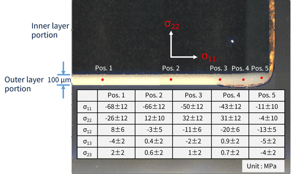 Fig. 5: Measurement positions and tria-axial stress analysis results for the MLCC cross section in the Y direction
Recommended equipment and software
- DicifferX Microarea Edition micro-area X-ray diffractometer
- SmartLab Studio II integrated X-ray analysis software (Powder XRD Plugin)