Application Note RACCT9025
About the sample: 3D printed plastic
3D printing, or additive manufacturing, is a process of making a three-dimensional object by adding a small amount of material at a time according to a CAD (computed aided design) file. This technique can be applied to various materials, including plastic, metals, ceramics, composites, and even food. 3D printing does not require a mold and is a great way to produce customized parts or prototypes fast and at a low cost. Another benefit of 3D printing is that it allows near-net-shape production of a part with complex internal structures. The catch is that you can't see and evaluate these internal structures from the outside of the completed part. It is where X-ray CT (computed tomography) technique can help by scanning the entire volume non-destructively, including the internal dimensions and defects.
Analysis procedure
- In this example, a 3D printed part was scanned using a micro-CT scanner, CT Lab HX.
- The external and internal surfaces of the parts were detected using the ISO-50 surface determination technique.
- The entire part shape measured by X-ray CT was compared to the original CAD drawing.
1. CT scan
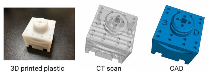
A roughly 50 mm size 3D printed plastic part was scanned to produce the 3D grayscale CT image. The picture of the sample, its CT scan, and the original CAD drawing are shown in the figure.

2. Surface determination
The surfaces of the parts were detected using the ISO-50 surface determination technique. At this point, you can do simple measurements such as distances and angles.

3. Nominal vs actual comparison
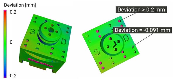
The nominal vs actual comparison is a direct and overall comparison of the CAD drawing (nominal) and the measured object dimensions (actual). The deviation between the CAD and measured dimensions is color-coded in the figure. Green indicates a good agreement while red and blue indicate the part being larger and smaller than the designed dimensions, respectively. Pink indicates areas where the deviation is out of the tolerance (0.2 mm in this case).

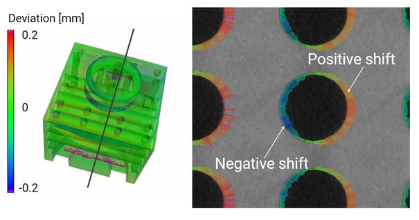
Because X-ray CT scans the entire volume of an object, not only the external surfaces but internal structures can be compared to the CAD drawing. A CT cross-section is shown on the right in the figure with positive and negative deviations for the internal structures indicated with blue and red lines. The length of the lines indicates the magnified deviation.


