Evaluation of Grain Condition and Orientation of Cemented carbide using 2D XRD
Introduction
Crystal grain conditions dramatically influence observed 2D XRD images, with fine grains appearing as rings and coarse grains as spots. If the intensity distributions along the rings are uniform, the corresponding phase has no preferred orientation. If the intensities appear as broken lines, the corresponding phase has preferred orientation. In the classical approach, XRD software only attempted crystal phase identification after converting a 2D diffraction image to a 1D profile. Information about grain conditions in the 2D diffraction image was not used. The Powder XRD plugin for SmartLab Studio II uses both the 2D diffraction image and the 1D profile derived from it for analysis. Using phase identification results and the 2D diffraction image together, the grain condition and orientation of each phase in a sample can be visually confirmed.
Measurements and results
A cemented carbide material tip was measured. Figure 1 shows a 2D diffraction image and the associated 1D profile with phase identification results. WC, TiC and C (diamond) were present in this sample. The peak intensity ratios of C and TiC were vastly different from the standard ratios in the powder diffraction database. In the 2D diffraction image, the diffracted X-rays from C were captured as spots and those of TiC as rings with heterogeneous intensities. This indicates that C was coarse-grained and TiC had preferred orientation.
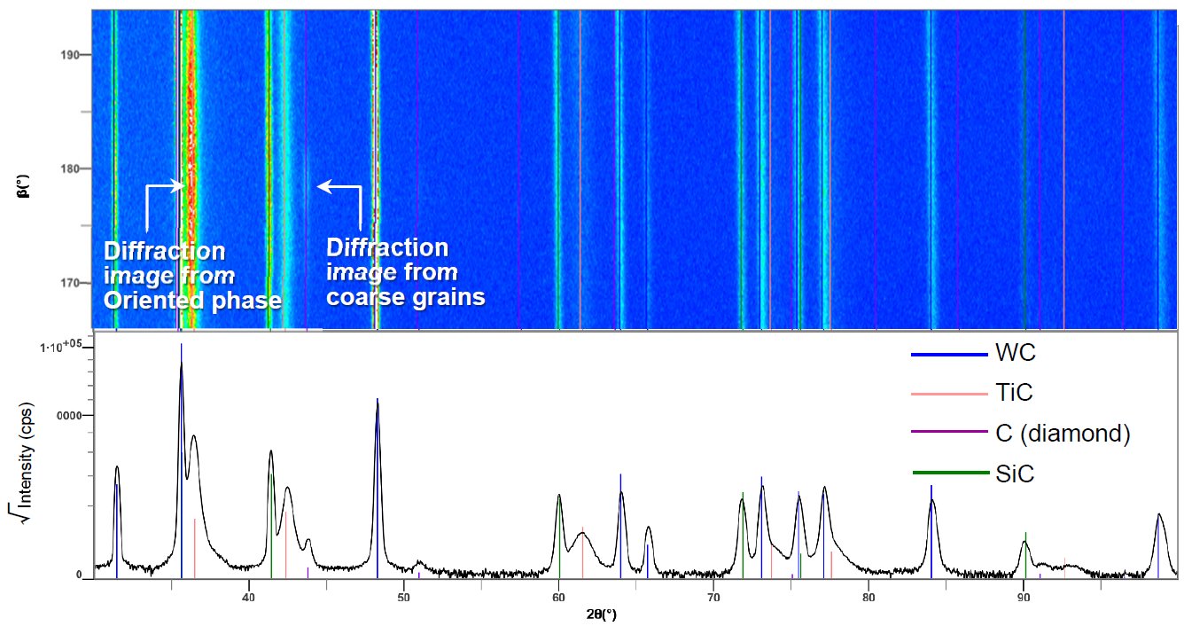 Figure 1: The 2D diffraction image and 1D profile with phase identification results.

Contact Us
Whether you're interested in getting a quote, want a demo, need technical support, or simply have a question, we're here to help.