Crystal Phase Identification of Carbide Tips by Micro-area 2D X-ray Diffraction
Introduction
Carbide tools used for cutting are provided with various types of coatings to improve durability. Previously, evaluation of the coating layer has been done using X-ray diffraction, but some users want to achieve rapid and simultaneous evaluation of factors such as site-dependent differences in composition, crystallinity and orientation. These evaluations can be easily done by employing the optical element and detector used in this report.
Measurements and results
Normally, the X-ray source used for X-ray diffraction measurement is a line-shaped beam, but by using the CBO-f optical element, it is possible to focus the line-shaped beam into a point-shaped beam, without any drop in intensity. In addition, using a 2-dimensional detector improves detection efficiency, and enables measurement of samples having trace components and orientations with weak diffraction intensity. Figure 1 shows an observed image of the measurement site on a carbide tool, and Figure 2 shows the 2-dimensional diffraction image of the carbide tool obtained using a CBO-f convergent optical element and a hybrid pixel array multi-dimensional detector HyPix-3000.
The 2-dimensional diffraction images obtained, respectively, from the carbide tools of Company A and B were converted to diffraction intensity with respect to the angle 2θ, and then identification was performed. As a result, there was confirmed to be a difference in coating layers, as indicated in Figure 3.
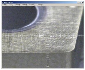 Figure 1: Observed image of measurement site on carbide tool
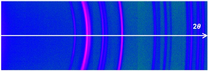 Figure 2: Two-dimensional diffraction image obtained using a CBO-f convergent optical element and a hybrid pixel array multi-dimensional detector HyPix-3000
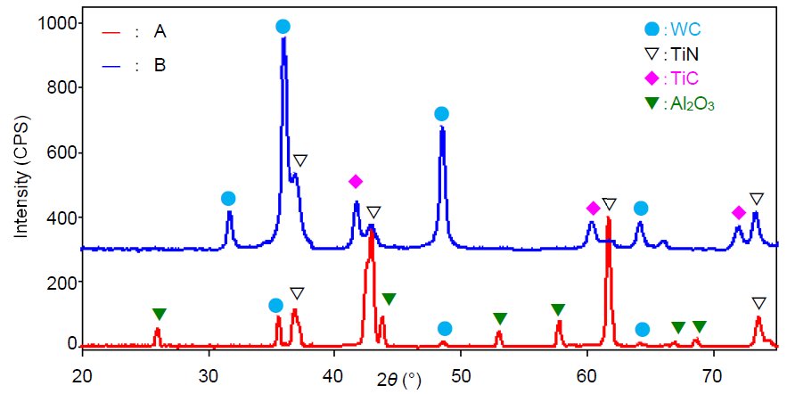 Figure 3: X-ray diffraction patterns obtained from carbide tool made by Company A and carbide tool made by Company B, and results of qualitative analysis

Contact Us
Whether you're interested in getting a quote, want a demo, need technical support, or simply have a question, we're here to help.